Introduction to 3D Design Using SketchUp
PROJECT OVERVIEW
- This introductory course provides an overview of all the essential elements of SketchUp skills needed for design, layout, and modeling 3D products. This course is intended for participants with little or no 3D design, 3D drawing, or SketchUp experience, but who want to create 3D models and products using SketchUp.
PROJECT MATERIALS/LINKS
- Computer (Windows or Mac supported)
- SketchUp Web is supported starting from basic laptops such as Chromebooks to high-end computers with dedicated graphics cards (for increased speed/rendering of 3D assets).
- Mouse
- Using a mouse is highly recommended to more accurately design objects in 3D.
- SketchUp Web App Link
- https://app.sketchup.com/app?hl=en
- This link will serve as the primary login address to access the SketchUp Web application that will be discussed in this course.
- SketchUp Web Help Guide from Trimble
- https://help.sketchup.com/en/sketchup-web/sketchup-web
- The team at SketchUp has also created a helpful repository that will be a useful reference for any questions or information that can be a helpful addition to the concepts and topics discussed in this lesson.
PROJECT OUTLINE
- Lesson 1: What is SketchUp?
- In this lesson, students will learn about the uses of SketchUp to create basic 3D models. For the purpose of this course, students will use the SketchUp for Web app which can be accessed online and does not require an application download.
- Lesson 2: Learning the SketchUp Toolbox
- In this lesson, students will learn about many of the different tools that are used in the SketchUp Web application.
- Lesson 3: SketchUp Project
- In this lesson, students will be given three different 3D modeling projects to recreate their own versions of SketchUp Web.
Lesson 1: What is SketchUp?

For this course, the free version of SketchUp will be utilized known as that runs in a web browser. It is a simple application where you can simply draw and create 3D models. The goal is to enable you to create anything you can imagine in 3D and without requiring a paid application or subscription.
The main link to access SketchUp Free app can be found here:
https://app.sketchup.com/app?hl=en
In order to use Sketch Free, each user must create a Trimble account:

It is easiest to sign in with an Apple or Google email account.
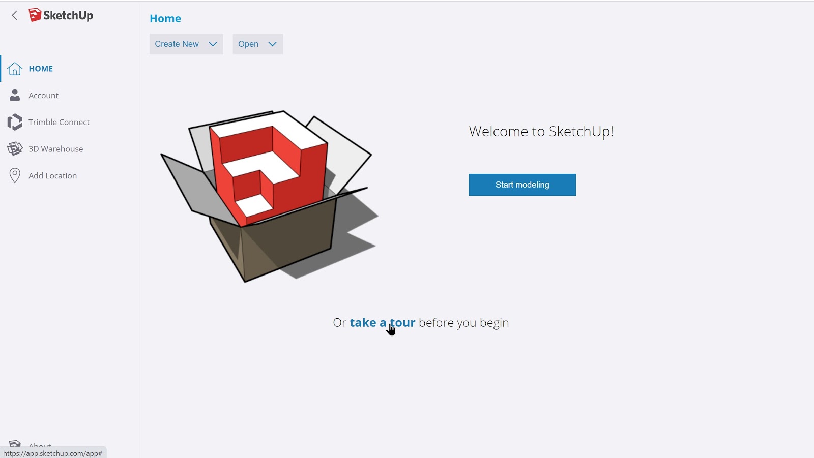
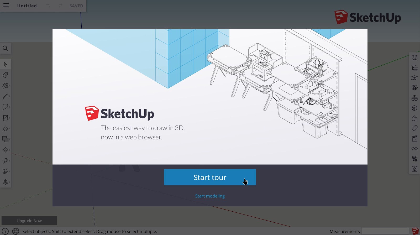
Once signed in, it is advised for all new users to view the basic tour of the SketchUp Web app to learn about its many features and the locations of each of the tools.
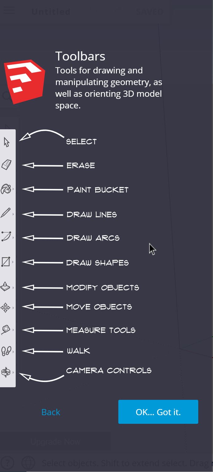
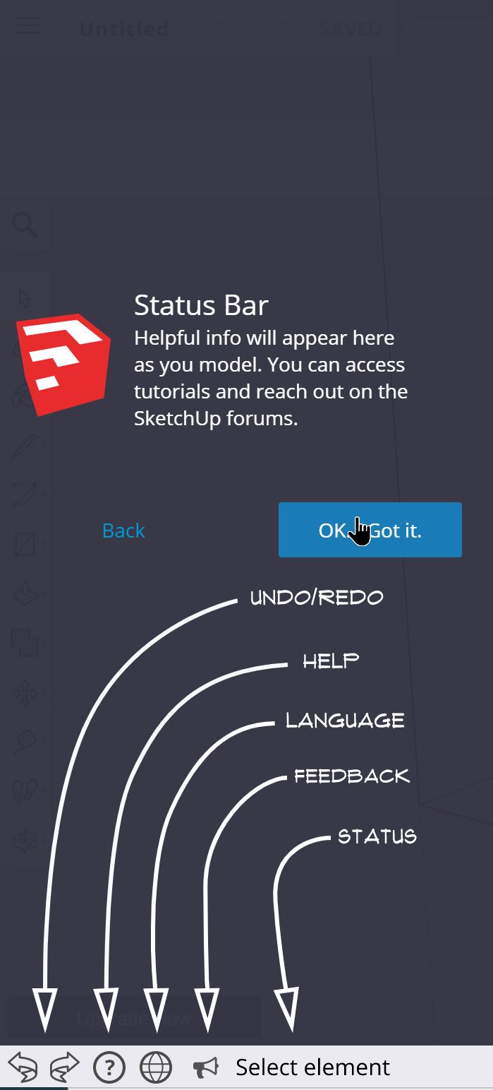
The basic tour of the app will include the following:
The tour will also display the names of all of the tools that can be accessed within the web app.


Once the tour is finished, it will take you to a blank project page to get started!
With the basic tour out of the way, now it’s time to learn how to sketch in 3D!
Lesson 2: Learning the SketchUp Toolbox
2.1 – Choosing a project template:
When signing in, there will be an option to start a new SketchUp project. By clicking on the ‘Create New’ icon, there will be a choice of options in whichever corresponding units are desired for the 3D object being constructed.

2.2 – Reviewing the main tools of SketchUp
The main tools of SketchUp can be found on the left side of the 3D modeling interface. For this section, each of the main tools will be explored.
2.2a Basic navigation
One of the primary steps of using SketchUp is understanding how to view the 3D model(s) properly to make the most of the available tools. There are a variety of main viewing tools that will be used.
They include: Zoom, Pan, and Orbit.
2.2b Zoom Tool:
For this tool, users can utilize their middle mouse scroll wheel to zoom in and out of a scene of a 3D model. They can also use the zoom icon found in the viewing tools menu on the bottom left of their interface where they are able to select the zoom tool and use it by holding down their left mouse button and sliding it up or down.

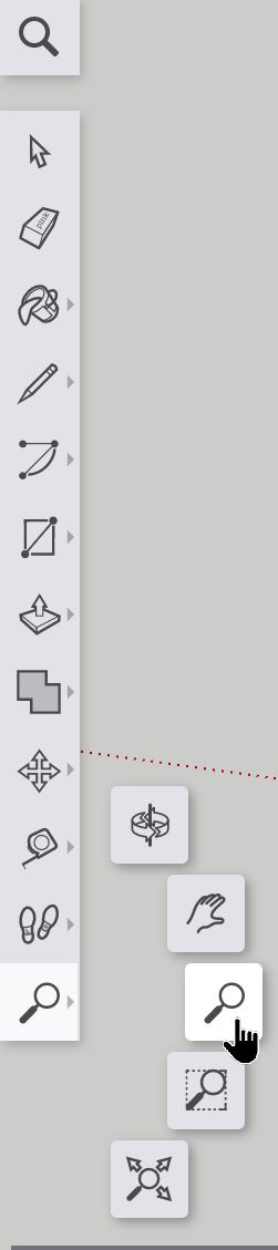
There are also the ‘Zoom Extents’ and the ‘Zoom Window’ options that will allow the user to resize their screen to view the entirety of the model they are designing in case they get lost or to highlight a particular area to zoom into.
2.2c Pan Tool:
To slide the viewer around a particular area from within a frame, the pan tool is highly effective at doing so. The icon looks like a left hand found in the same menu as the zoom tool.
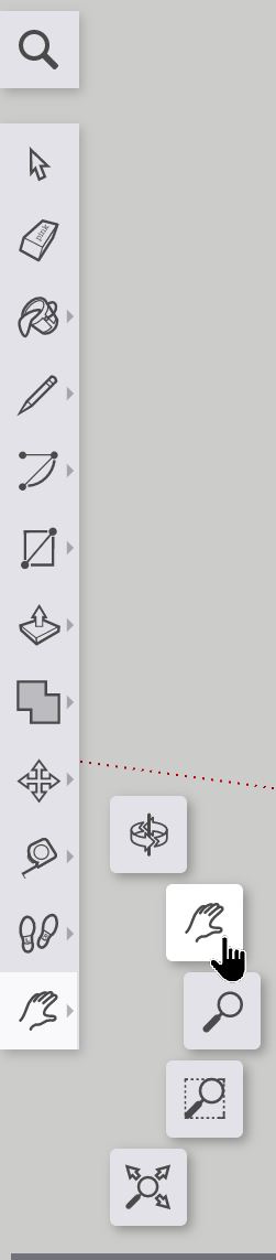
Using the Pan tool, holding down the left mouse button while sliding in any direction will allow the user to move the camera about a particular frame of a 3D model. This will allow the user to view different areas of the model in a frame to work on it.

2.2d Orbit Tool:
The last of the viewing tools, the orbit tool can be used to rotate the camera around the center of the screen around the area of interest within the 3D model. The orbit tool can be recognized by the rotating arrows in the same menu where both the zoom and pan tools can be selected.

To use the orbit tool, use the left mouse button while holding it down and moving the mouse to rotate the camera about the center of the screen to change the angle at which the viewer is displaying the 3D model being worked on.
2.3 Understanding the XYZ axis
An important concept when working with any 3D software is understanding the 3 axes, X, Y, and Z, that will all affect the placement of 3D sketches and assets within the application interface.
Each of the axes are color coded within the SketchUp Web app interface.
Blue corresponds to the Z axis (height)
Red corresponds to the X axis (length)
Green corresponds to the Y axis (width)
Proper use of the viewing tools to understand which axis or axes will be sketched upon when using the drawing tools is an important concept when designing any object.
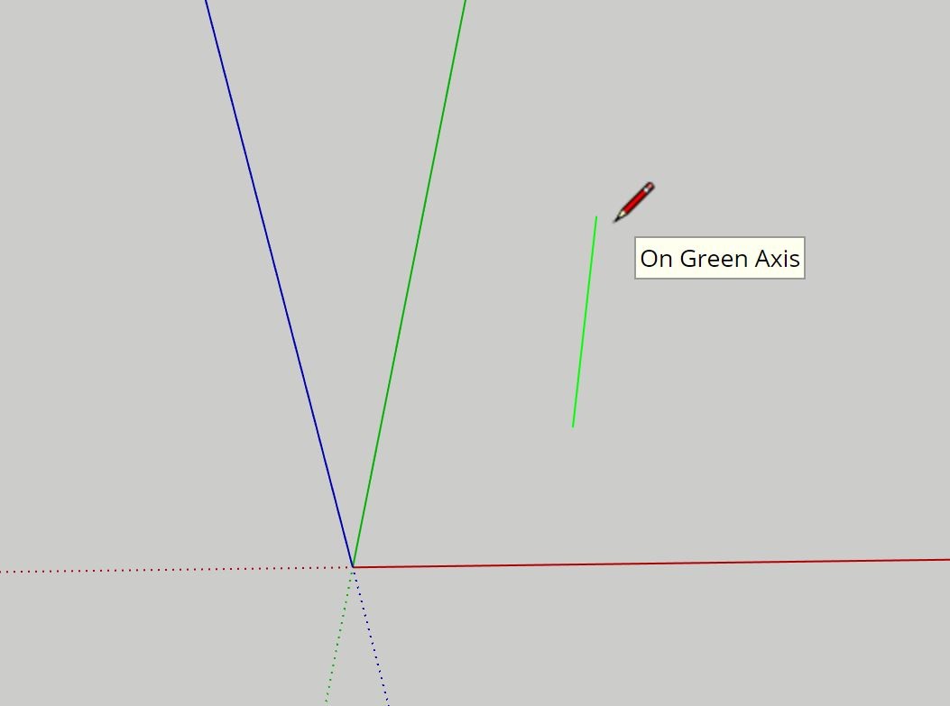
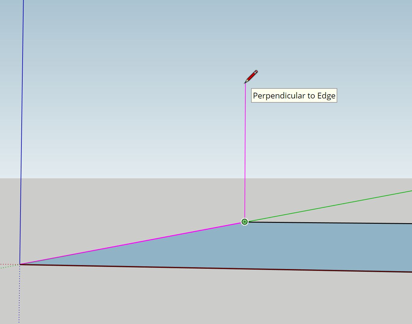
When using SketchUp, for example when using the line (pencil) tool, when drawing along a particular axis, the app will color-code with the specific color of the axis that is being drawn on to assist the user with alignment.
Example 1: Drawing along the blue axis (height)

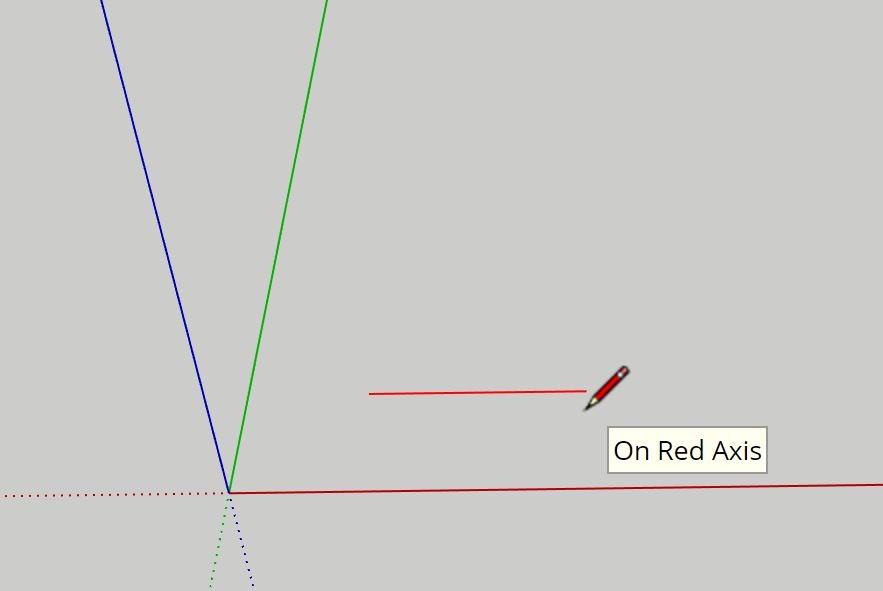
Example 2: Drawing along the red axis (width)
Navigating between each of the axes will be paramount to accurately adding in shapes, lines, curvature, etc. to any 3D model to avoid placing geometry where it is unintended. If a line or curve being drawn is not corresponding to a particular axis, the sketch will appear in either black or a mixture of colors, including purple which will indicate the drawing of a line or curve in both the Z and X-axis (the corresponding colors blue and red combining to make purple).
Now it’s time to practice using tools!
2.4 Drawing and using the line (pencil) tool
The line tool is one of the most important tools when starting a sketch. It is used primarily to draw line segments across a plane or across a face of a 3D model to include additional shapes and/or geometry to the plane that can be further manipulated with other tools. It can be found at the top of the left toolbar.
To use the line tool, click on the icon to change the mouse cursor into the line tool and bring it to the plane that will be sketched on.

After clicking on a particular area and dragging the mouse in the desired direction, a line will appear that will be of varying length.
To lock a line in place, click the mouse at the desired length and the line will be produced. Upon the completion of this initial line, the tool will attempt to connect another line from the endpoint of the first line. In order to prevent additional lines from being drawn, hit the ESC key on the keyboard to cancel the line tool to stop it from sketching undesired lines.
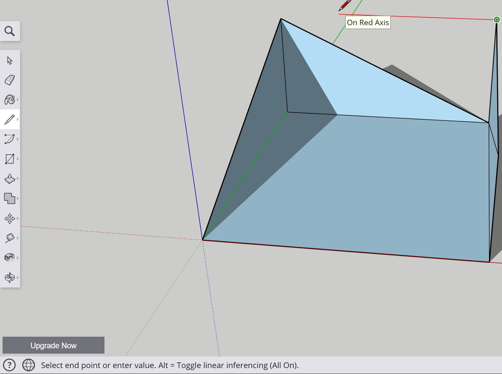
Example (below): Drawing along the Red Axis

When first learning to use the line tool, make use of the color indicators to help visualize the direction and plane with which each line will be drawn. Creating intersections and closed faces will result in the SketchUp app filling the gap between lines and creating what is called a “face.”
Currently, in the app shown above, the faces of the model are colored in light blue and a shadowing effect is being applied to the viewer to assist with viewing the particular model being drawn.
2.5 Using the measuring tools
In addition to having the accurate units desired for a 3D model, whether in inches, centimeters, millimeters, etc., an important set of tools to verify the accuracy of a sketch or 3D model are the different measuring tools offered from within the SketchUp app.
These tools include the: tape measure tool, protractor tool, and text tool (used to annotate areas of a model with specific information such as length, shape, etc.).
2.5a Tape Measure Tool

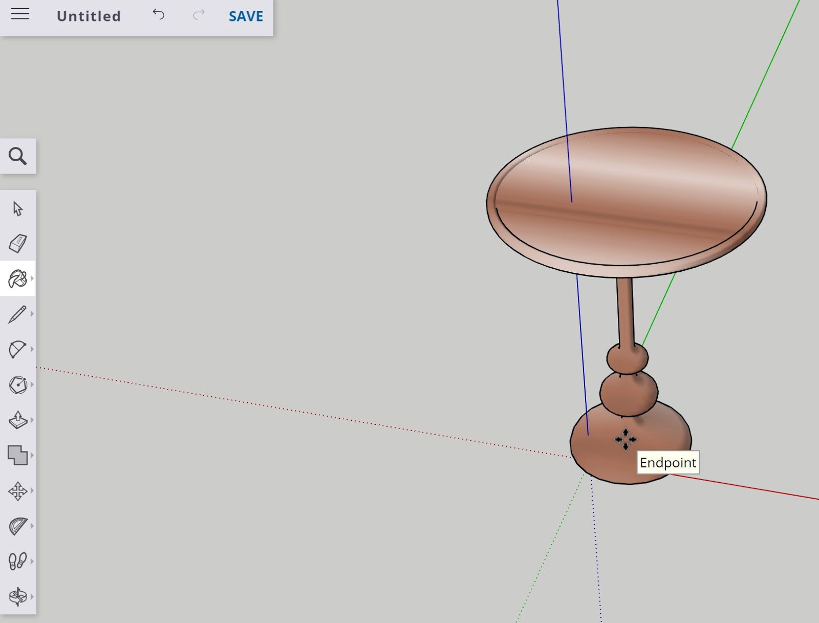
The tape measure tool can be found on the lower end of the left toolbar and is used to measure distances between endpoints in a 3D model and also to create guidelines to assist with sketching parts of a 3D model.

After selecting the tool, the mouse cursor will change as it does with any other tool to reflect the tape measure tool being enabled. To use the tool, click on any vertex, surface, or point from without the 3D model and then drag the mouse to the desired distance and click once more to confirm the measurement.
Looking at the bottom right of the application, the measurement will appear for the length that was measured using the tool in the units set for the 3D model off the template (inches vs. centimeters, etc.) selected at the beginning. The measurement will also display as a pop-up nearby the cursor once two endpoints are selected.
2.5b Protractor Tool

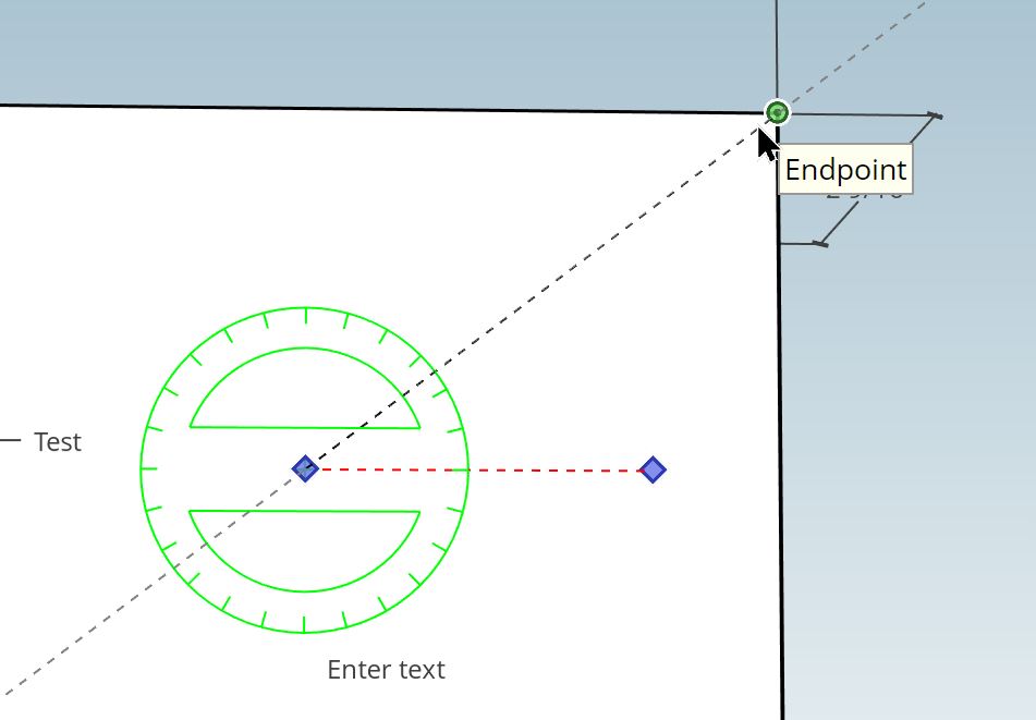
The protractor tool is used to measure angles and set guidelines at specific angles to assist with the placement of lines and objects.
The protractor tool can be found in the same menu where the tape measure tool is found at the lower end of the left toolbar.
Once selected the protractor tool will display a silhouette of the measuring end of the tool which can then be applied to a surface on a 3D model to measure angles and also to create specific guidelines along the degrees needed (up to 360) that will lock on to the face of that particular model.
2.6 Creating, editing, and moving parts of a 3D model
Now that basic viewing, sketching, and measurement have been covered, the next step is to learn how to manipulate parts of a 3D sketch.
The tools to be covered include the following: select tool, move tool, and erase tool.
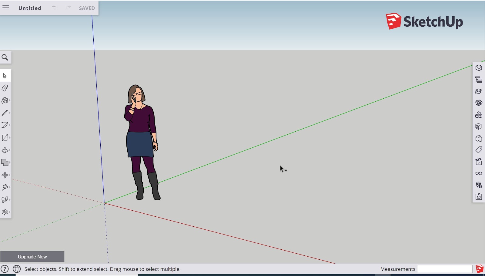
2.6a Using the select tool
The select tool can be found at the top of the left toolbar denoted by the arrow icon.
By clicking the object using the left mouse button in conjunction with holding down the shift key, it is possible to select multiple parts of a 3D model to manipulate. It is also possible to use the tool by clicking the left mouse and dragging across the entirety of the 3D model to select it.
Using the select tool, an object can be selected along a number of different parts that include:
An edge: Referring to any visible line on the 3D model
A face: Referring to a closed polygon ‘side’ of a model with at least 3 sides
A point: Referring to a vertex at the end of a corner or where points join together
The select tool is highly useful for applying larger effects to a 3D model including moving it around, resizing it, coloring it, etc.
2.6b Using the move tool
Now with the select tool covered, the following tool, the move tool, can be used to position an object about the workspace as well as stretch and move different elements of a 3D model.
The move tool is found near the center bottom of the left toolbar and is denoted by the 4 arrows pointing in 4 directions.
When selected, the movement tool will allow the user to click and drag around the selected object, edge, face, or vertex wherever their mouse cursor is pulling from.
Using the tool in conjunction with the select tool is an important part of repositioning a 3D model while it is being worked on, especially if it has multiple components to it.


2.6c Using the erase tool
Not every step taken in 3D sketching and modeling will be perfect. Oftentimes it will require multiple steps to adequately draw the intended component of a 3D model and there will be a need to erase unnecessary entities within the model.
The erase tool can be found at the top end of the left toolbar denoted by the eraser icon.
After selecting the tool, it is now possible to delete parts of a model by highlighting (holding down the left mouse button and dragging it across an area of the model) edges or vertices of a 3D model and then releasing the left mouse button to delete the highlighted surfaces
It is also possible and very useful to delete items by selecting it with the select tool and hitting the ‘delete’ key on the keyboard.
2.7 Creating shapes SketchUp
In order to convert a 2D sketch into a 3D model, there are additional tools that can be used to generate different shapes of varying sizes and specifications.
The tools to be explored will include:
Push/Pull Tool
Rectangle Tool
Circle Tool
Arc Tool
Shape Tools
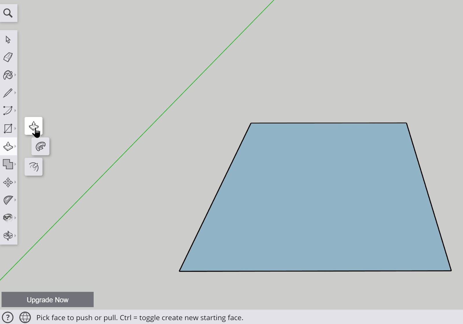
2.7a Using the push/pull tool
In order to convert a 2D sketch into a 3D object, the push/pull tool can be used. It is located near the lower center of the left toolbar and is represented by the flat square with an arrow pointing upwards.
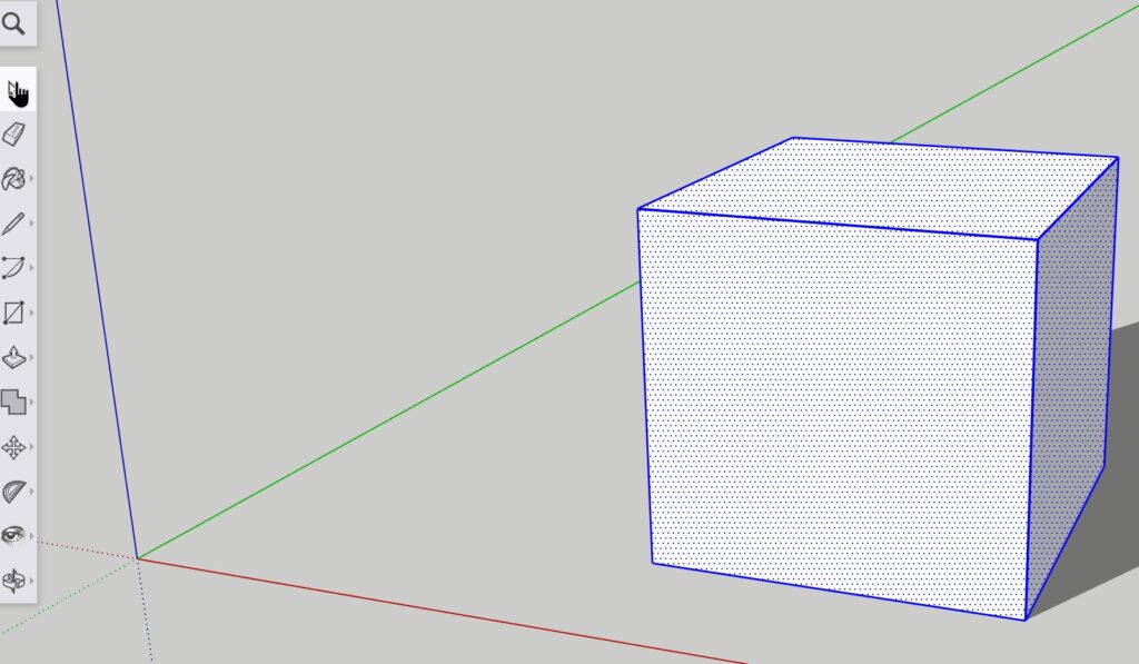
Once selected, the tool allows the user to drag a face on a sketch or 3D model and drag it in a particular direction that will extend the geometry of the sketch to a desired length. In the example below, the light blue shaded square is the area with which the push/pull tool can be used to extend the face of the sketch.
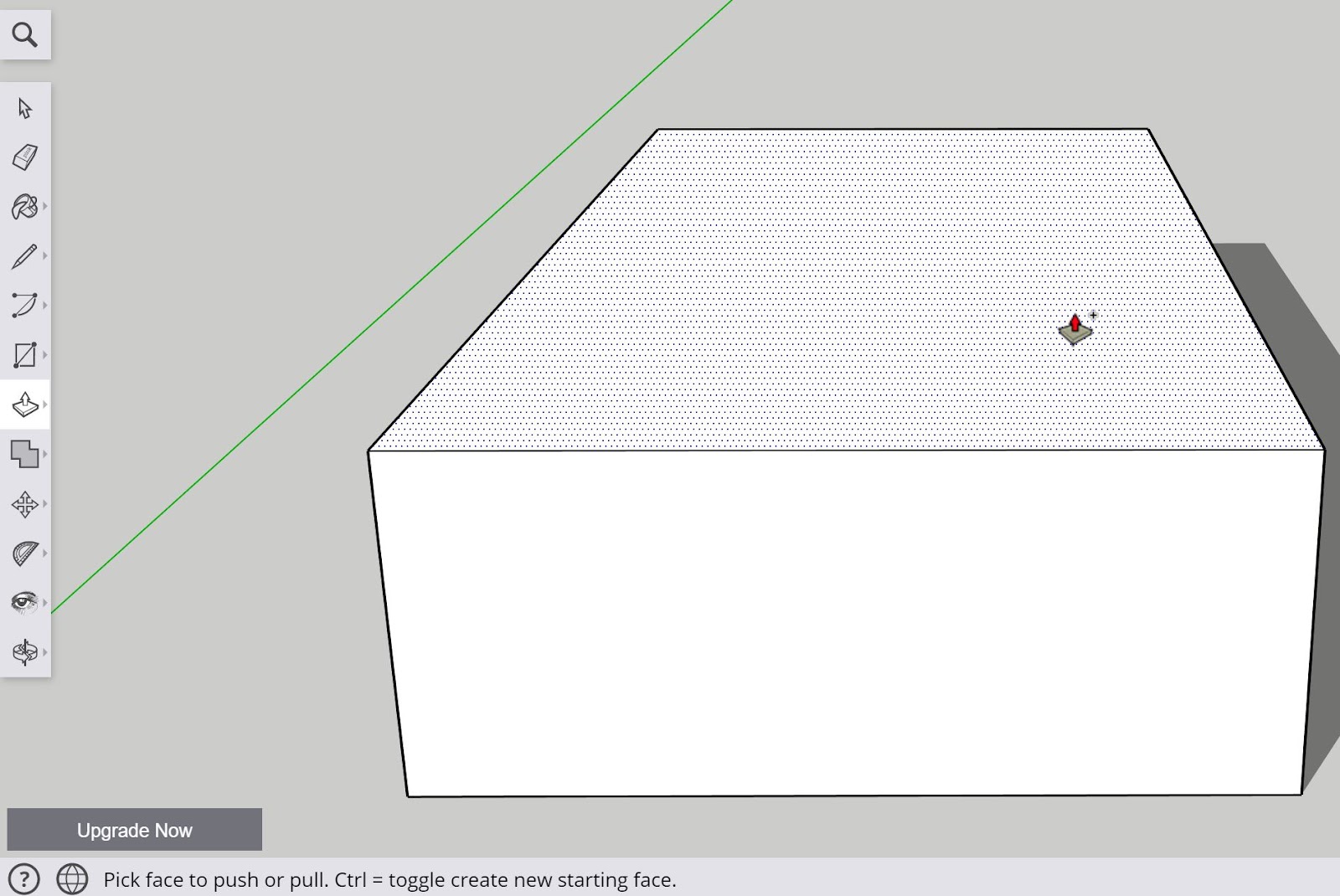
Depending on which face is highlighted with the tool, different faces can be stretched in whichever direction is desired depending on the direction that the face is dragged using the left mouse key held down and moved in the particular direction needed.

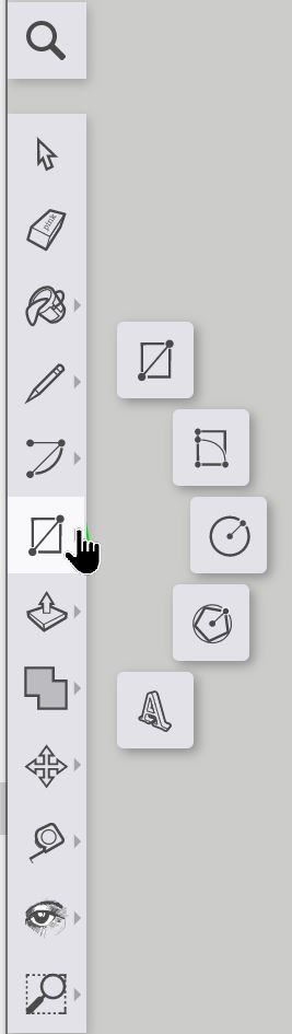
2.7b Using the rectangle tool
The rectangle tool can be found in the middle of the left toolbar and is the top option as shown below with a rectangle icon with a diagonal line between two vertices.
In order to use the tool, similar to that of the pencil tool, the left mouse button is used to pick a point to draw the rectangle and, while holding down the left mouse button, a rectangle of desired length and width can be drawn. Once the desired length is highlighted, a subsequent left mouse click will confirm the shape and the rectangle will appear (shown in the image below with a light blue shaded face). 

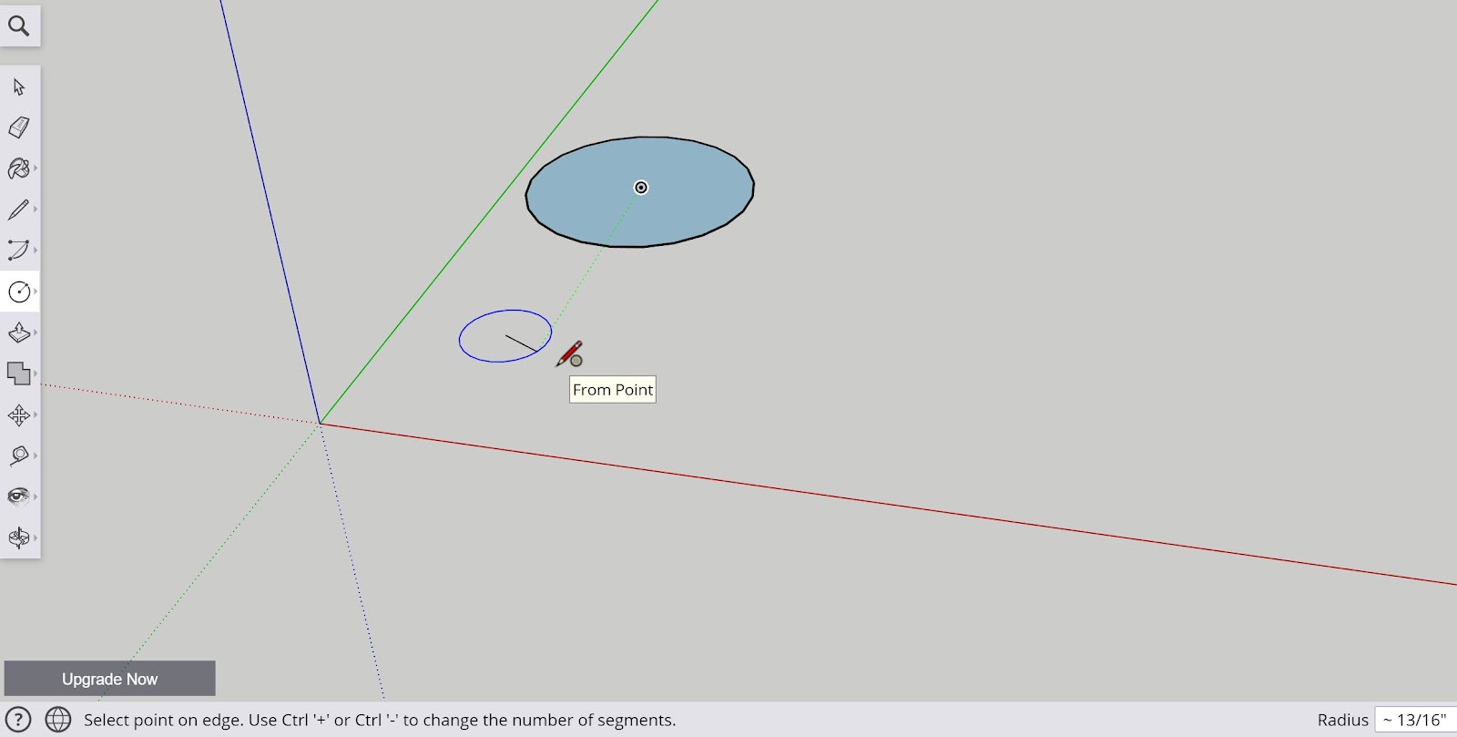
2.7c Using the circle tool
Another useful shape tool is the circle tool. Located in a similar location to the rectangle tool, the circle tool behaves in a similar manner where a midpoint is selected for the circle using the left mouse button and radius of the circle can be manipulated by moving the mouse in a particular direction. Once a desired radius is selected, another left mouse click will confirm the shape and the 2D circle will be confirmed into the workspace.
2.7d Using the arc tool
While not necessarily a shape tool, the arc tool is helpful for producing curvature in a 2D sketch that can later be transformed into a 3D model or component in addition to the desired end project.

The arc tool is located at the top center of the left toolbar and it has a variety of different subtools.
These include:
Arc tool
2 point arc tool
3 point arc tool
Pie tool
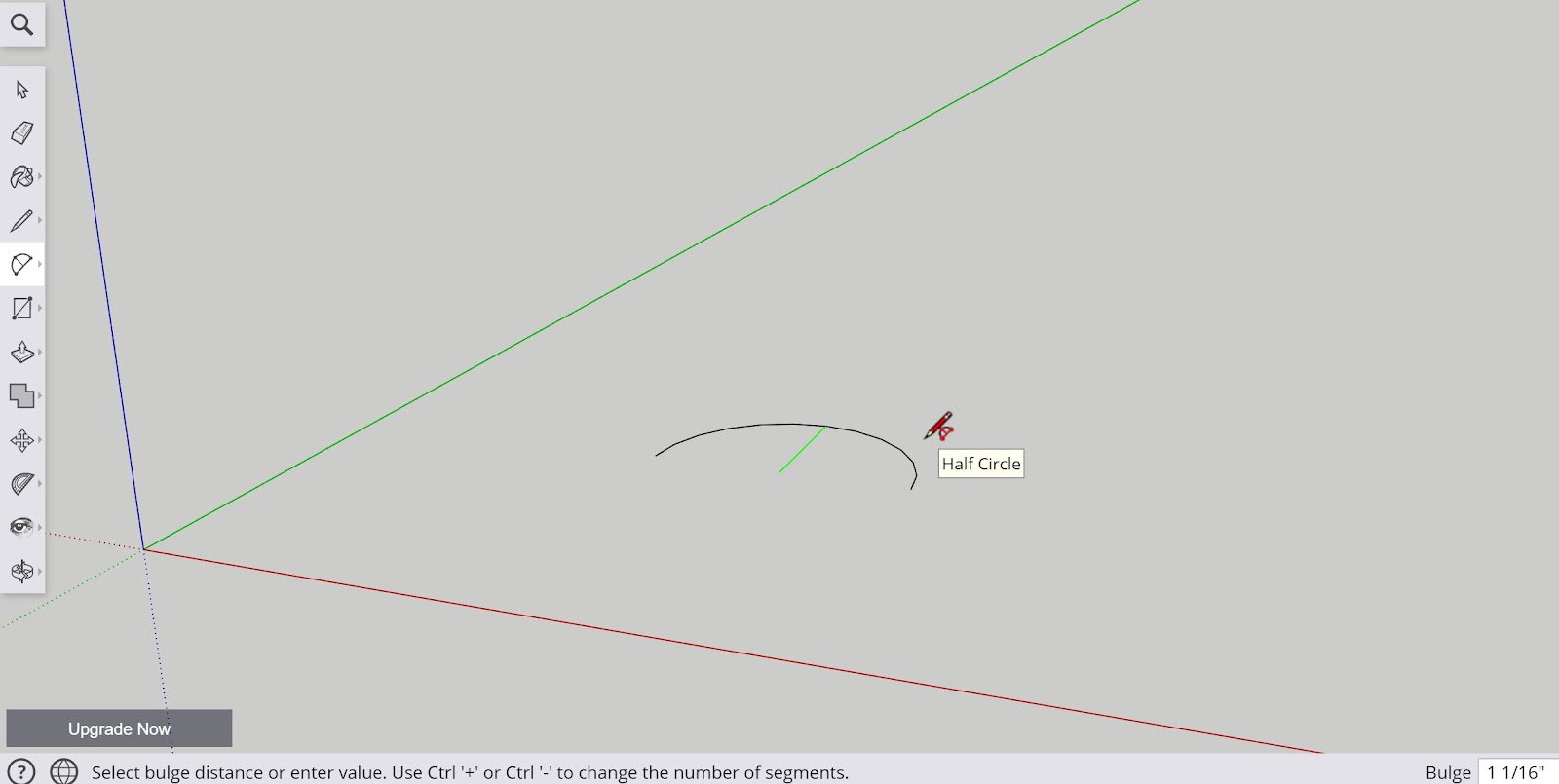
For the purposes of this course, the main arc tool that will be used will be the 2 point arc tool which is the second option of the four presented in the submenu.
In order to use the 2 point arc tool, once selected a starting point for the first point of the arc must be selected on the desired point of the workspace or existing sketch or 3D model. Once this first point is selected, a secondary point must be selected from which an arc will be produced by moving the mouse in the desired direction which will create the arc at the specific width and length as needed.
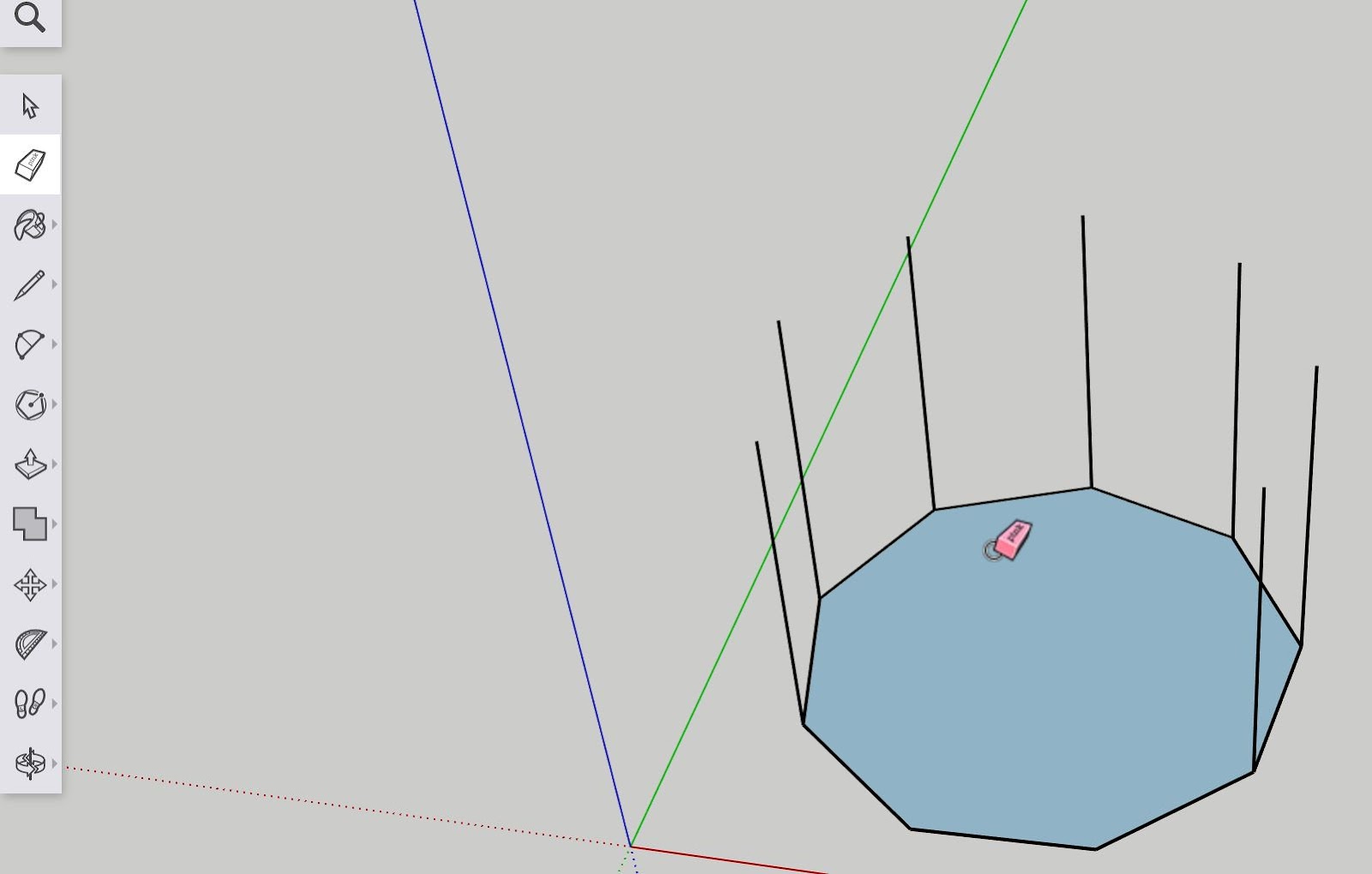
2.7e Using the polygon tool
In addition to basic rectangles, circles, and arcs, the SketchUp Web app allows the user to create polygons of different shapes and sizes that can be manipulated by the tools covered in the course.

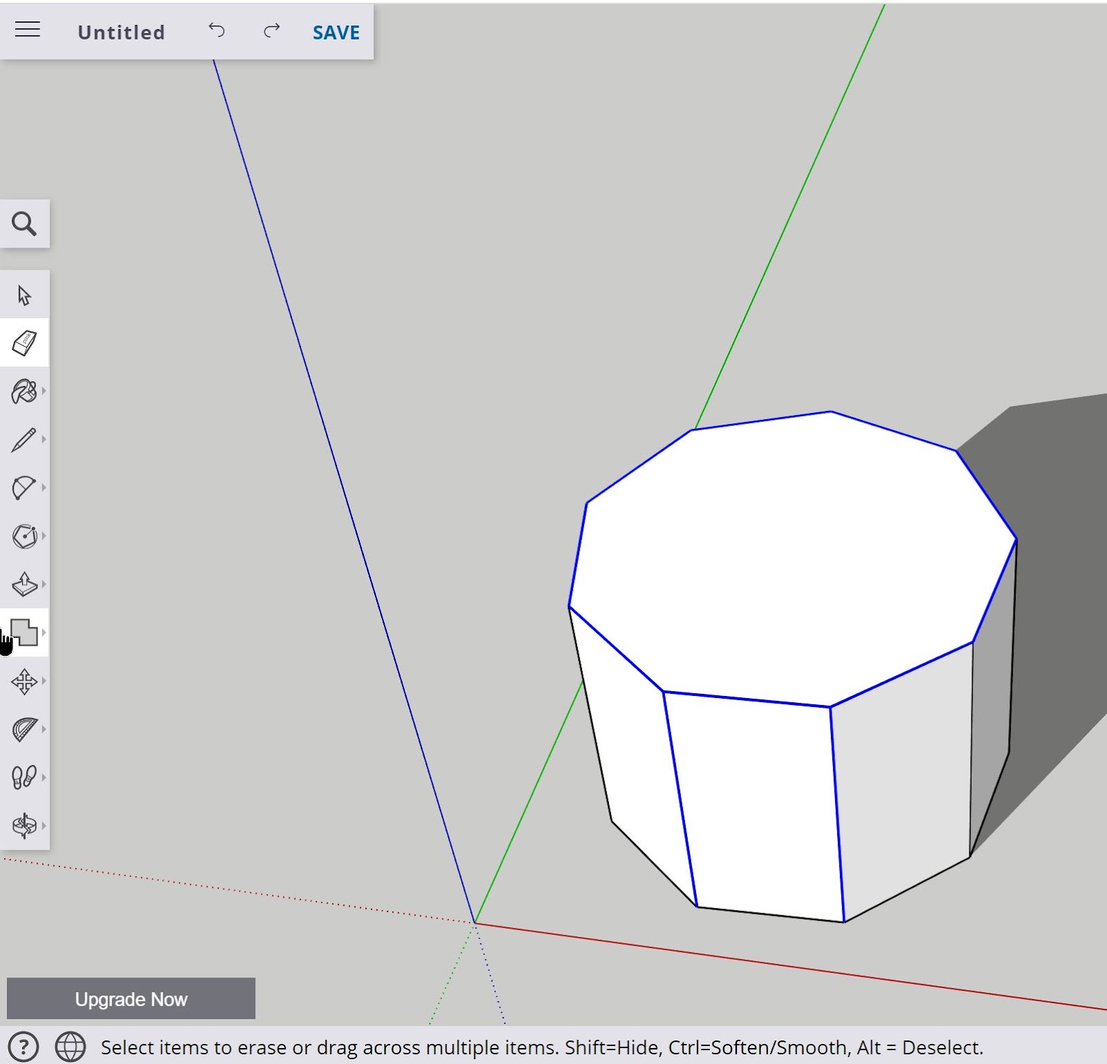
The polygon tool is located in the center of the left toolbar in the shapes category and is denoted by the circumscribed pentagon.
The polygon tool has two modes that include the ‘circumscribed’ and ‘inscribed’ modes that will change the way the edges of the polygon are created (whether they point inwards or outwards) depending on how many sides are specified in the construction of the polygon. This feature is controlled using the ‘CTRL’ key and can be used once an area of the workspace is selected with the left mouse button while toggling the polygon tool.
The number of sides in a polygon can be modified using the ‘CTRL’ and ‘+’ keys used together as well as ‘CTRL’ and ‘-’ keys depending on how many sides the user wants in the shape. The minimum requirement is 3 sides in order to produce a face on the sketch.

2.8 Additional useful tools
In this section, there will be two additional tools to be explored that will be helpful additions in customizing and discovering new perspectives to a particular model or project being designed.
These tools are the:
Paint Tool
3D Warehouse Tool
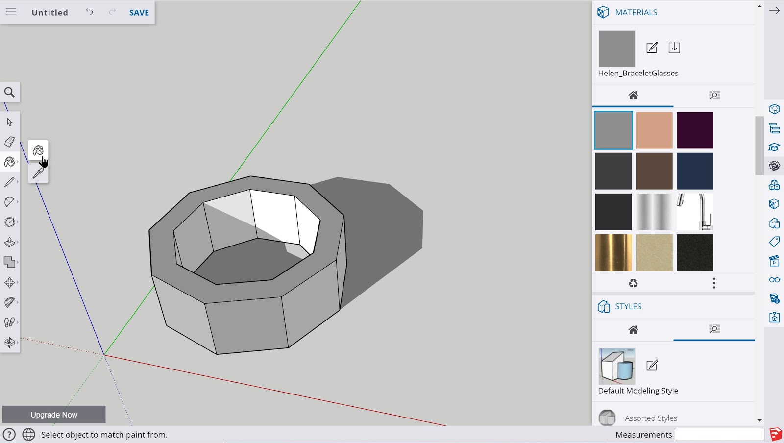
2.8a Paint Tool
Once a project is near completion and the necessary tools and geometries are constructed, the paint tool can be used to add colors and textures to different faces on the 3D model.
The paint tool is located at the top of the left toolbar and is denoted by the paint bucket icon. Once selected, the mouse cursor will be changed to the paint tool and a color or texture can be selected from the ‘Materials’ menu on the right side of the screen that can then be applied to any open face of the 3D project.
SketchUp Web offers many varieties of colors and textures so it is advisable to explore the many options available before applying them to a particular 3D design.

2.8b 3D Warehouse
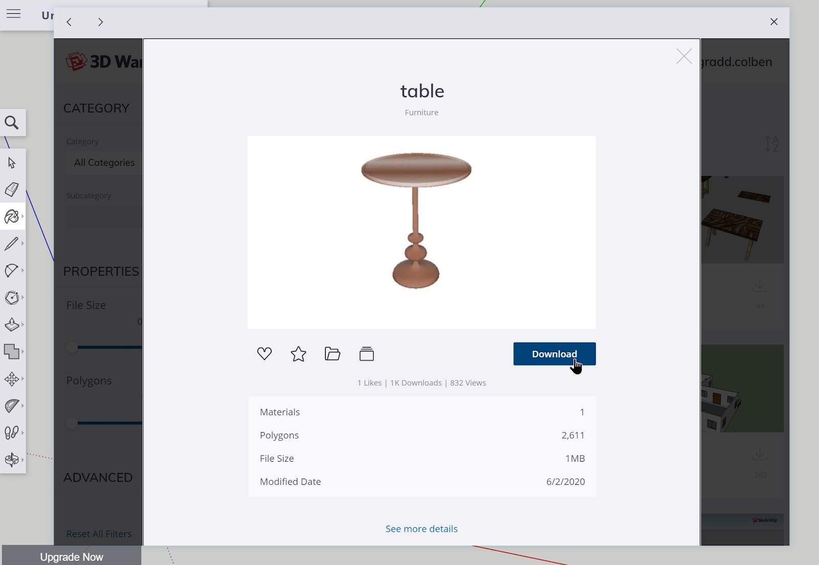
The last tool to be covered in the course is the 3D Warehouse Tool or option available on the right toolbar. One of the best features of SketchUp is the vibrant community that continues to upload and share an enormous quantity of 3D models, sketches, tutorials, and other helpful tools/extensions that SketchUp learners can tap into for inspiration and assistance for a particular object.
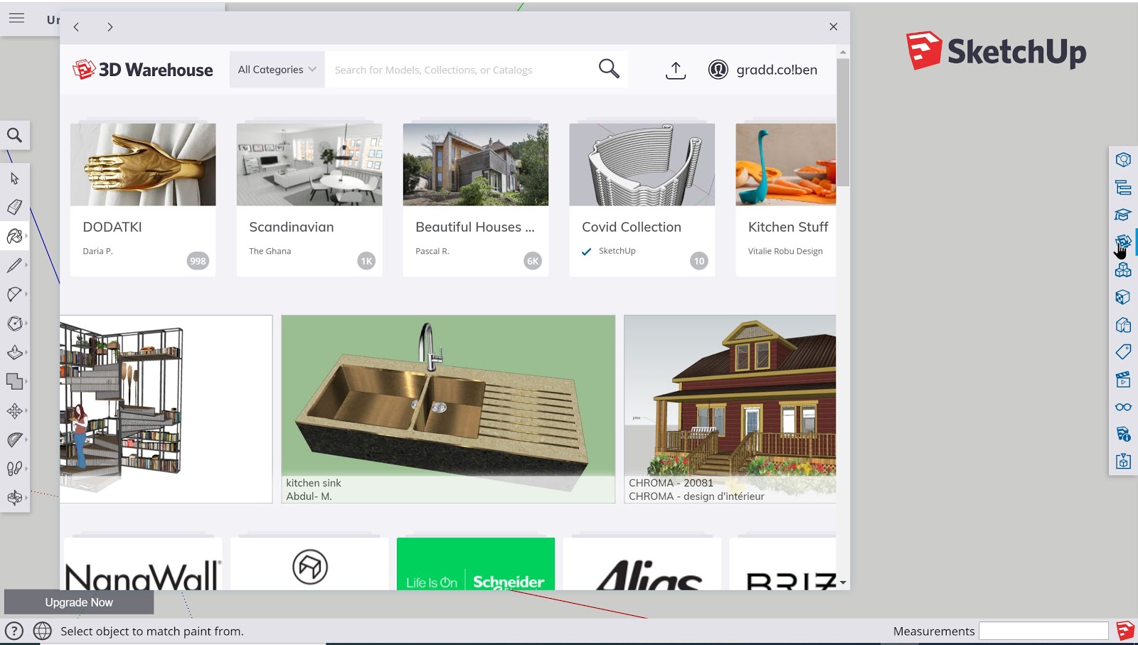
In many cases, it will be easier to import in a 3D model of an intended design that can be traced, copied, or viewed to help a user complete their project. In order to use the tool, once selected a popup menu will cover the screen and the user can type in or select the desired 3D asset they would like to import into their workspace.
Once a selection is made, a user can download and insert the 3D model into their workspace so they can make use of it as they wish.

Lesson 3: SketchUp Projects
In this lesson, there will be a variety of projects from a number of SketchUp learning resources for learners to practice their sketching and 3D modeling skills using the SketchUp web application.
The projects vary in terms of difficulty and are accompanied by helpful tutorial guides as well as videos that will supplement the instructions provided.
Project #1: Creating Your First Aircraft
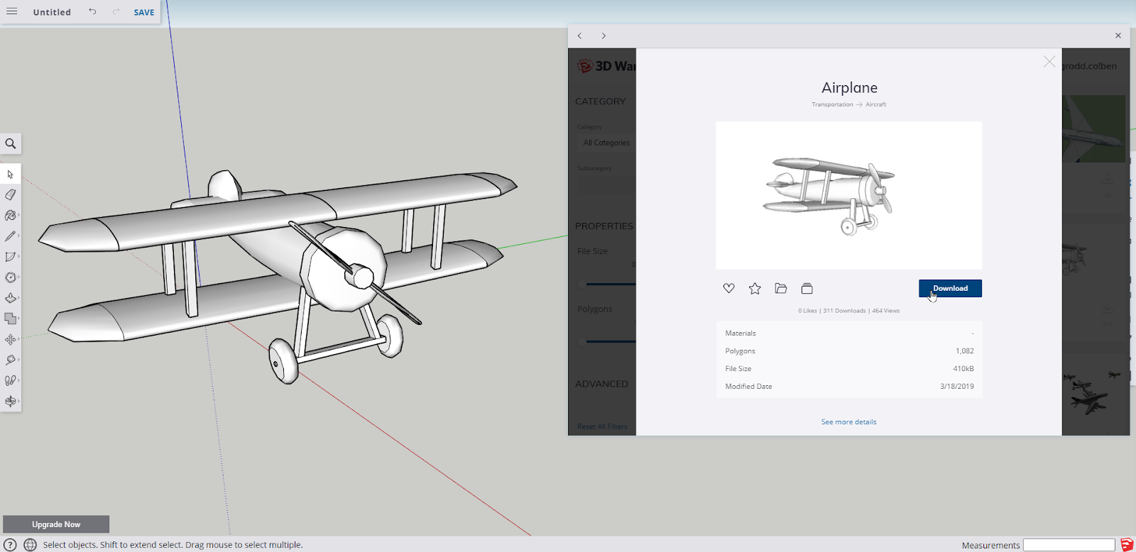
The objective is to use the basic tools from SketchUp web to create an aircraft of their own. What is advised for this project is to import (download) a 3D model of an aircraft of choice that can assist the user with tracing, copying, or referencing the necessary components of the aircraft.
A helpful video series to create an RC aircraft can be found below which will teach the basics of SketchUp into the construction of an RC aircraft that can be manufactured and tested live – a cool part of the potential of 3D modeling and design!
https://www.flitetest.com/articles/sketchup-for-rc-aircraft-design-tutorial-1
Project #2: Sketching a Floor Plan into 3D
In this project, the objective is to take a 2D picture of a floor plan and upload it into SketchUp in order to trace and construct a 3D floor plan.

To complete the following project, visit this link to get a detailed guide with videos on each step:
https://designerhacks.com/sketch-floor-plan-to-3d-in-sketchup/
*How to insert images into the SketchUp web app
Using the toolbar at the top of the app interface, click on the 3 dashed lines to open up a menu. Select the ‘Import’ option from the list, and then when prompted on where to upload the image from, select the ‘Your computer’ option and locate the desired image. The file formats supported by SketchUp are also displayed.


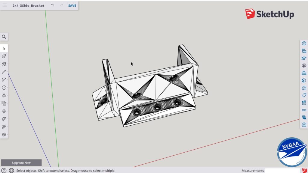
Project #3: Creating a Custom Bracket
With the rise of 3D printing among students of all ages, one of the most useful applications of 3D modeling is creating custom items that can be used in one’s home or workplace.
For this project, the objective will be to create a custom bracket using SketchUp.

The example above was created to address the need for brackets used for 2×4 lumber. After sketching and testing several iterations of the bracket design, a final version was ultimately selected and is now in use in various applications!
To complete the following project, the following tutorial will outline the steps necessary:
https://mastersketchup.com/sketchup-tutorial-custom-bracket-3d-printing/
Course Conclusion:
With the completion of this introductory course, there are many further skills practice and projects to complete using SketchUp and many of the other popular 3D modeling applications available both in cloud format as well as downloads. Have fun Sketching!
PROJECT MATERIALS/LINKS
- Computer (Windows or Mac supported)
- SketchUp Web is supported starting from basic laptops such as Chromebooks to high end computers with dedicated graphics cards (for increased speed/rendering of 3D assets).
- Mouse
- Using a mouse is highly recommended to more accurately design objects in 3D.
- SketchUp Web App Link
- https://app.sketchup.com/app?hl=en
- This link will serve as the primary login address to access the SketchUp Web application that will be discussed in this course.
- SketchUp Web Help Guide from Trimble
- https://help.sketchup.com/en/sketchup-web/sketchup-web
- The team at SketchUp has also created a helpful repository that will be a useful reference for any questions or information that can be a helpful addition to the concepts and topics discussed in this lesson.


NVBAA
2900 Meade Avenue, Suite 8 | Las Vegas, NV 89102